VSAT|VSAT In Railways
VSAT System Architecture
A VSAT system consists of a satellite transponder, central hub or a master earth station, and
remote VSATs.
The VSAT terminal has the capability to receive as well as transmit signals via the satellite to other VSATs in the network.
Depending on the access technology used the signals are either sent via satellite to a central hub, which is also a monitoring centre, or the signals are sent directly to VSATs with the hub being used for monitoring and control.
Types of VSAT
There are two types of VSAT Satellite
a. Bi-Directional Operation - The dish both sends (uplinks) and receives (downlinks)
information.
b. Receive-Only Operation - The dish receives (downlinks) information only.
VSAT Topologies
The network of VSATs at different locations adopts different topologies depending on the end
applications traffic flow requirements.
These topologies could be Star or Mesh.
i. Star topology
The most popular of these is Star topology, where we have a big central earth station known as the hub.
Generally the hub antenna is in the range of 6-11metre in diameter.
This hub station controls, monitors and communicates with a large number of dispersed VSATs. Since all VSATs communicate with the central hub station only, this network is more suitable for centralized data applications.
Large organizations, like banks, with centralized data processing requirements is a case in point.
ii. Mesh topology
In a mesh topology a group of VSATs communicate directly with any other VSAT in the network
without going through a central switch.
A switch in a mesh network performs only the monitoring and control functions. These networks are more suitable for LAN & telephony applications.
These have also been adopted to deploy point to point high speed links. However, in actual practice a number of requirements are catered to by a hybrid network topology.
Under hybrid networks a part of the network operates on a star topology while some sites operate on a mesh topology.
VSAT SPECTRUM
Three ranges of spectrum make up VSAT are shown in table
Multiple Accessing Schemes
The primary objective of the VSAT networks is to maximize the use of common satellite and
other resources amongst all VSAT sites.
The methods by which these networks optimize the use of satellite capacity, and spectrum utilization in a flexible and cost-effective manner are referred to as satellite access schemes.
Each of the above topologies is associated with an appropriate satellite access scheme. Good network efficiency depends very much on the multiple accessing schemes.
There are many different access techniques tailored to match customer applications. Access techniques including stream, transaction reservation, slotted Aloha and hybrid mechanisms are used and are configurable on a per-port basis, enabling customers to run multiple applications simultaneously.
Voice of 5.6 Kbit/s Hughes-proprietary CELP compression as well as voice of 8/16 Kbit/s ADPCM compression schemes, synchronous data of 1.2 to 64 Kbit/s, asynchronous data of up to 19.2 Kbit/s and G3 fax relay are some of the applications.
Components of VSAT Terminal and Hub station
In contrast to the hub station, the remote terminals are much simpler.
To minimize total system costs, most of VSAT networks are designed to have a single expensive hub and a large number of much smaller remote terminals.
i. VSAT terminal
Remote terminal consists of several main subsystems which include:
a. A dish antenna: generally 0.55 to 2.4 m in diameter (though larger dishes are sometimes
required), which can be wall, roof or ground mounted.
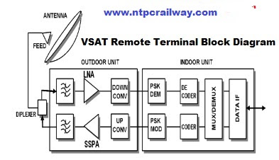
b. An outdoor unit (ODU): which contains the microwave electronics for the terminal?
This is usually the size of a shoe box, but it may be much smaller.
If the ODU is large it is normally supported on the antenna mount behind the dish.
Smaller ODUs can be attached directly to the rear of the feed assembly in front of the dish.
In case of Reception the ODU consists of:-
● Band path Filter which passes the wanted signal.
● Low Noise Receiver (LNA) inserts between the antenna and the earth station receiver
which pre-amplify the received weak signal.
● Down converter which changes receive frequency before feeding the demodulator into IF
signal (70 or 140 MHz) and if a combination of LNA and down converter built into one device attached to the feed this is called Low Noise Block(LNB).
But in case of Transmission the ODU consists of:
● Up converter which changes the 70 or 140 MHz IF to the required transmit frequency
before feeding it to the High Power Amplifier (HPA).
● Solid State Power Amplifier (SSPA) is a VLSI solid state device that is gradually replacing
Traveling Wave Tubes in satellite communications systems because they are lighter weight
and is more reliable, amplifies the up-converted signal before feeding the antenna. Output
powers of HPA are usually in the range 0.1–6W (Ku band) and are usually from 2-16W
(C-band).
c. An indoor unit (IDU): which provides the
● modulation, encoder & multiplexing (in case of transmission),
● demodulation, decoder & demultiplexing (in case of reception)
● Synchronization with the rest of the network and supports the user interfaces.
This box is usually about the size of a domestic video recorder. Remote terminals usually support a wide range of common electrical interfaces such as RS-232, RS-422, V.35, as well as
voice and TV.
Several common protocols are also generally supported including SDLC, 3270 bisync, X.25, async and Ethernet.
Fig. shows VSAT Remote Terminal Block Diagram.
Link availability is also usually designed to be high, with an end to end availability of better than
99.7% being quite common.
ii. VSAT Hub Station
The hub station consists of several main subsystems as shown in Fig; except for the
antenna these are usually fully redundant with automatic switchover in the event of failure:
A switch (generally a packet switch) which controls routing between host ports and the modulator and demodulator ports, as well as adding and reading header address information which controls routing to and from individual IDUs.
One or more modulators which modulate the outbound carriers with the stream generated
by the switch (each outbound carrier has a dedicated modulator).
A bank of demodulators which receive the inbound carriers and extract the data packets
and feed them to the switch.
An NCC (network control centre) which controls and monitors the operation of the hub and
the IDUs in the network.
An RFT (radio frequency terminal), which contains:
The transmit subsystem containing up converters which change the 70 or 140 MHz IF to the required transmit frequency before feeding it to the HPA.
Uplink power control is often provided so that the power transmitted by the hub can be increased to compensate for high link attenuation due to precipitation in bad weather and can also control the interference.
The receive subsystem consisting of a LNA and a down converter to change the received frequency to the IF frequency (70 or 140 MHz).
The antenna subsystem consisting of a large antenna (6 to 9 m in diameter) on a mount
with a tracking system which allows the antenna to follow the satellite as it moves very slightly in the sky.
Space Segment Support
The ideal orbit for a communications satellite is geostationary, or motionless relative to the
ground.
Satellites used for communications are almost exclusively in the geostationary orbit, located at 36000 km above the equator.
In line with ITU stipulations, for avoiding interference, all satellites are placed 2 degree apart.
This places a maximum limit of 180 satellites operating in a geostationary orbit.
i. Space segment
Space Segment is available from organizations which have procured satellites, arranged
launches and conducted preliminary tests in-orbit and who then operate these satellites on
commercial basis.
ii. Transponders
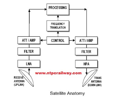
Contained in the satellite body are a number of transponders, or repeaters. These transponders
as shown in Fig perform the following functions:
● Signal Reception - it receives the signal uplinked by a VSAT and/or hub
● Frequency Translation - the frequency of the received signal is translated to a different
frequency, known as the downlink frequency.
The frequency translation ensures that there is no positive feedback and also avoid interference related issues.
● Amplification - the transponder also amplifies the downlink signal
The number of transponders determines the capacity of a satellite.
The INSAT series of satellites have typically 12/18 transponders in various frequency bands.
Each transponder typically has a bandwidth of 40 MHz.
VSAT advantages and Drawbacks
i. Advantages
● Great flexibility to accommodate growth and changes;
● Broadcasting and distribution/collection capabilities to/from remote locations;
● Distance insensitive, long haul communications, wide geographic coverage;
● Rapid installation of equipment at the customer’s premises with limited infrastructure
and independence from earth networks and infrastructure;
● Better (high) quality of services, very high reliability and high availability (99.9 %) is far
better than the availability of ground networks;
● Low maintenance requirements;
● Centralized control and monitoring;
● Large bandwidths allow high traffic speed and density;
● Emergency back-up.
ii. Drawbacks
● Loss of transponder may lead to loss of network; Communication links can be restored by
using a spare transponder.
● Propagation delay (using star topology, double hop = 0.5s).
This may prevent the use of voice communications, at least with commercial standards, in a
star shaped VSAT network.


0 Comments
You can give your Suggestions and feedback here